Key Features
- High-performance filter design with LTSpice simulations.
- Comparison between Butterworth and Chebyshev filters.
- Optimized stability and frequency response for circuit applications.
Comparison Criteria
Ripple Voltage
Roll-off Rate
Voltage Gain
Poles and Zeros
Frequency Response
Transfer Function, Q-Factor
Design
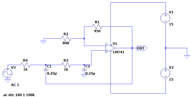
Figure 1: Butterworth Filter Circuit
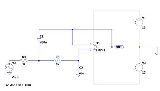
Figure 2: Chebyshev Filter Circuit
Experimental Steps
Both Butterworth and Chebyshev filters were designed and analyzed using LTSpice simulations. The following steps were carried out:
- Construct circuits in LTSpice.
- Calculate frequency cut-off.
- Perform AC Analysis to observe ripple voltage.
- Analyze roll-off rate and frequency response.
- Perform transient analysis at different frequency ranges.
- Generate Poles-Zeros plots using MATLAB.
- Compare theoretical values with simulation results.
- Discuss findings and conclusions.
Simulation Results
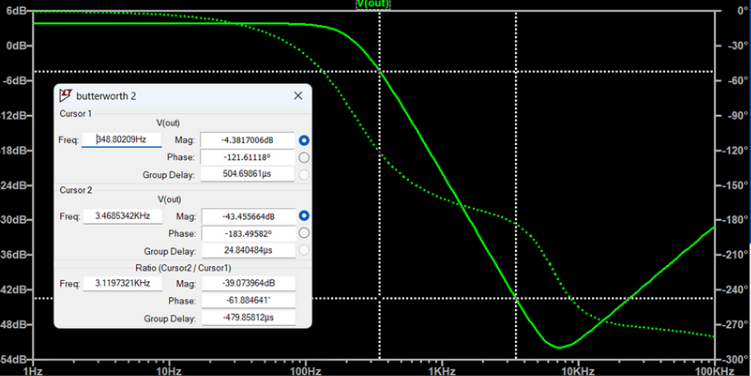
Figure 3: Butterworth Simulation Roll-off rate Result
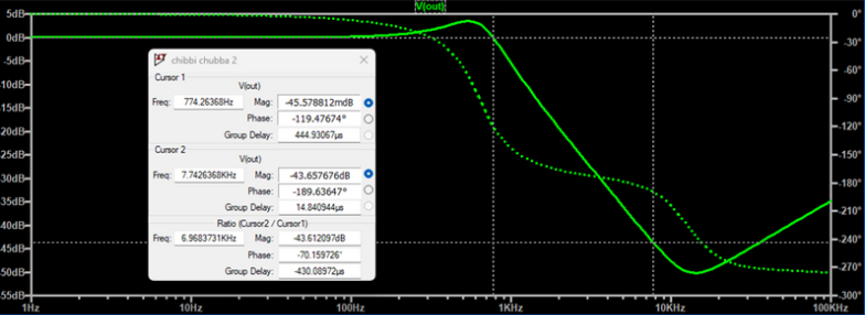
Figure 4: Chebyshev Simulation Roll-off rate Result
Comparison Table
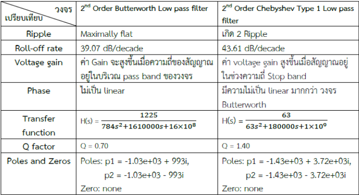
Figure 5: Filter Comparison